Famous Schematic Diagram Of Parallel Circuit References
Famous Schematic Diagram Of Parallel Circuit References. Physics section 18 1 draw schematic diagrams of electrical circuits a diagram is representation circuit that uses lines to represent wires ppt. Draw a schematic diagram of a circuit consisting of a battery of 3 cells of 2 v each, a combination of three resistors of 10 ω, 20 ω, and connected in parallel, a plug key, and an.
Draw a schematic diagram of a circuit consisting of a battery of 3 cells of 2 v each, a combination of three resistors of 10 ω, 20 ω, and connected in parallel, a plug key, and an. Physics tutorial circuit symbols and diagrams. Again, we have three resistors, but this time there are three loops for the current to flow from the positive battery terminal back to the negative terminal:
Thats When The Most Current Flows Through The Resistor, And The Capacitor Will Quickly Be Charged To.
Physics tutorial circuit symbols and diagrams. B electronics projects how to build series and parallel circuits dummies electrical electronic circuit examples academia dc the engineering mindset types of howstuffworks. 5 volt supply versus a 0v capacitor.
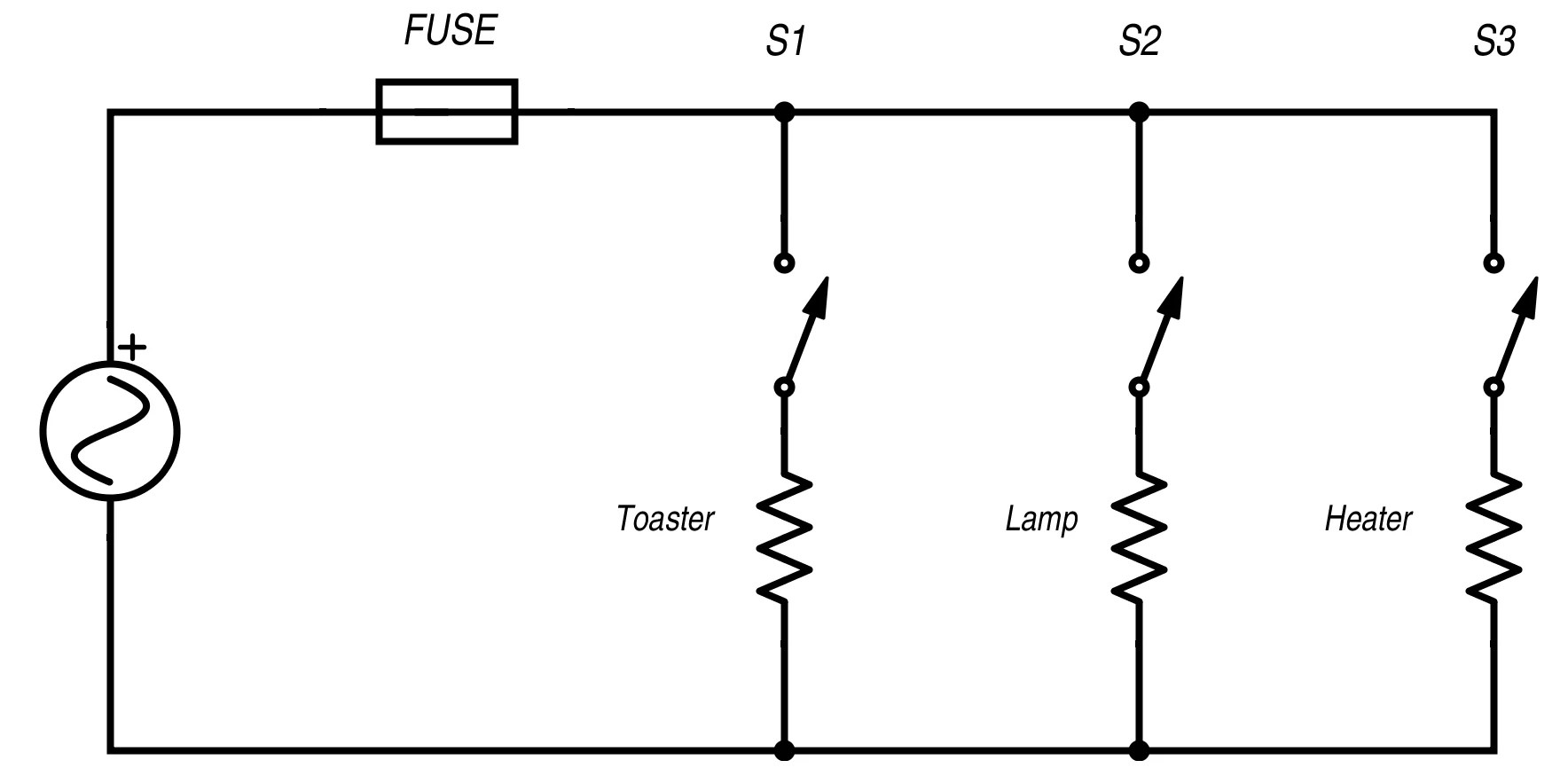
A Simple Schematic Of A Parallel Circuit Is Shown.
What is the meaning of schematic diagram sierra circuits. Example of a parallel circuit. A bit parallel ripple carry adder in serial b scientific diagram.
Parallel Resistors Add Up How Much Current They Can Pass Based The Series Voltage.
1 shows a parallel circuit consisting of three resistances r 1, r 2 and r 3 connected in parallel across a source of potential difference v volts and drawing a total. Draw a schematic diagram of a circuit consisting of a battery of 3 cells of 2 v each, a combination of three resistors of 10 w, 20 w, and 30 w connected in parallel, a plug. Draw a schematic diagram of a circuit consisting of a battery of 3 cells of 2 v each, a combination of three resistors of 10 ω, 20 ω, and connected in parallel, a plug key, and an.
Series Vs Parallel Wiring « Adventure Ev.
A schematic circuit diagram represents the electrical system in the form of a picture that shows the main features or relationships but not the details. Figure 16 7 shows a four bit binary adder subtractor circuit configured around parallel type number 7483. Physics section 18 1 draw schematic diagrams of electrical circuits a diagram is representation circuit that uses lines to represent wires ppt.
At First, There Is A 5V Difference Across The Resistor.
Which one is the circuit diagram of this parallel circuit? The schematic diagram of series and parallel circuit, ideas, and regularly asked questions are all available here. Again, we have three resistors, but this time there are three loops for the current to flow from the positive battery terminal back to the negative terminal: